Nothing grand to start with, but as a first project I thought to combine a 20×4 LCD display with two DS18B20 temperature sensors to monitor indoor and outdoor temperatures. This would replace a cheap display I had been using but was sceptical on its accuracy.
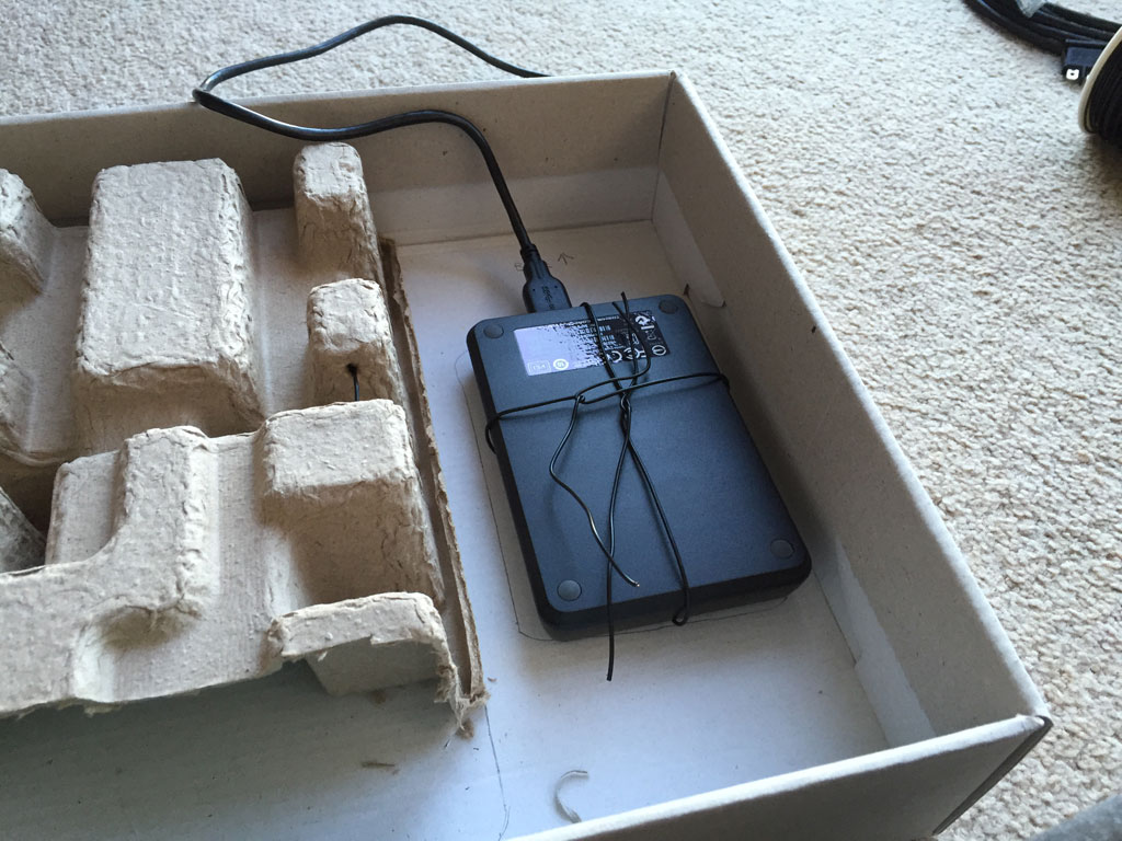
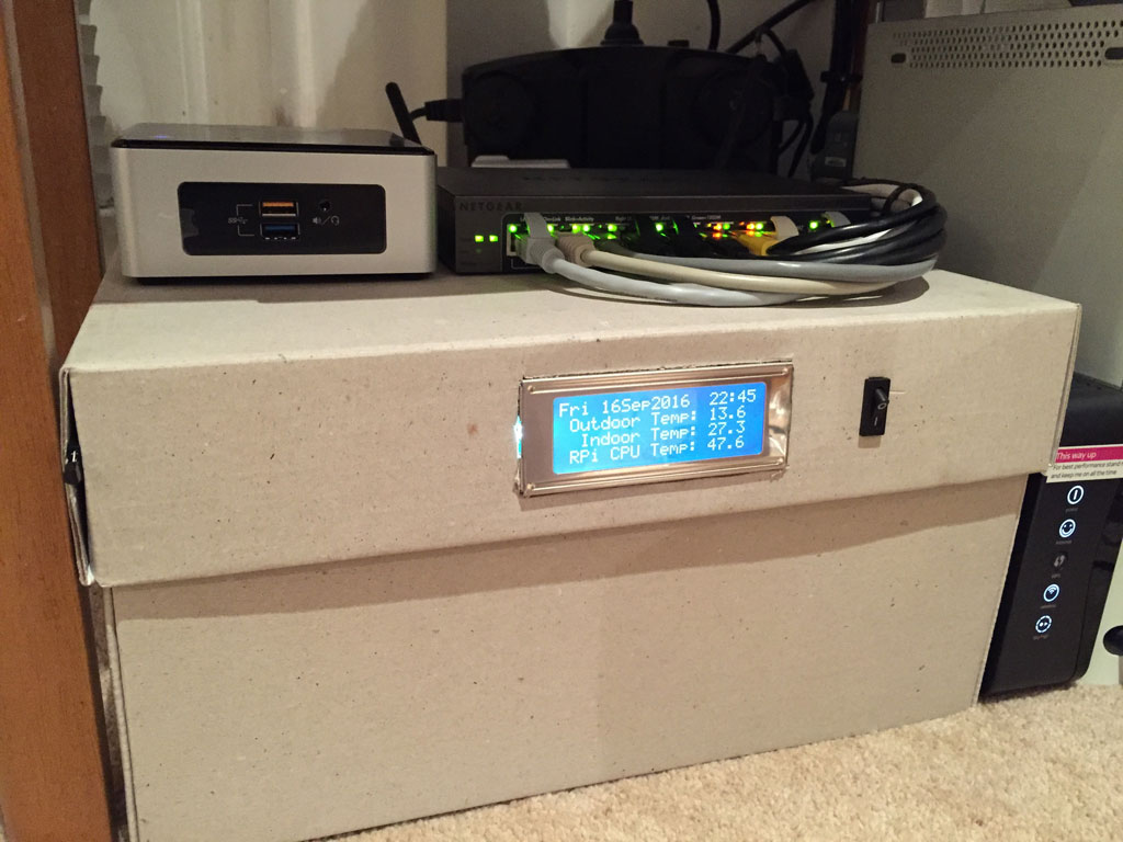
Getting the basics right involved making the device blend in to the current setup without the usual mass of wires protrude. From the last round of the seam ably endless cable management war I used a shoebox base as a stand for the webserver and network switch, with the box hiding the various power bricks and extra cable, with most coming from the Xbox 360. Still having the shoebox lid I thought it would be good to use as a modular part to house the Pi and display.

Case chosen, I used some box packaging as a spacer to allow the lid to fit on the box base, with the lid overhanging bit a few millimetres to allow the lid to fit over the base. Then a chance to layout the machine within the voids.
As the Pi and drive would have ended upside down, I decided to use wire and hot glue to suspend them from the lid as a crude cage, hanging them between the base and top allowed to maximise cooling.
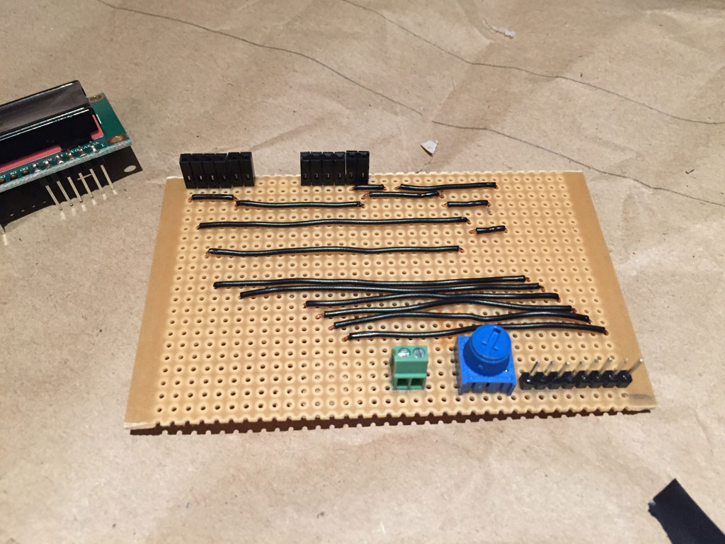
Now for the screen, after successful breadboard testing, I converted it onto a piece of stripboard. As it was one-sided stripboard all connectors had to be on the same side, but luckily there was enough room to allow all connections and still have the screen flush to the box. The board design was modified to integrate a switch to provide power to the LCD backlight LED.
Measuring from the outside, a hole was cut for the screen and another for the switch that supplied power to the LCD backlight. Inserting and checking fit for the screen and switch the header cables were connected to the GPIO pins of the Pi.
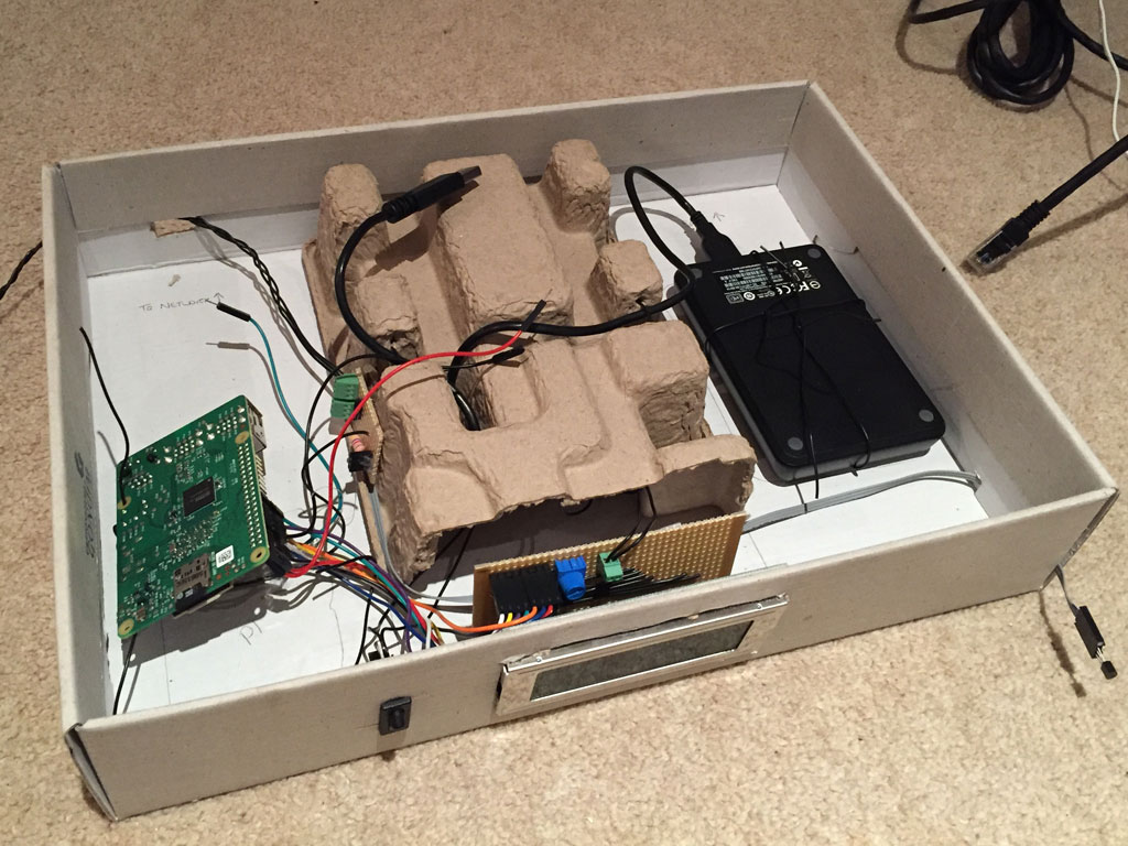
Next the temperature sensors, connecting via the GPIO pins of the Pi, these connected to a small piece of stripboard that acted as a connector to the DS18B20 chips to allow easy, modular access to them, and positioned to the rear of the case. I used pin headers to connect the indoor sensor, connected with wire salvaged from an old PC, and a 2.54mm PCB terminal block connecter to wire the external sensor.
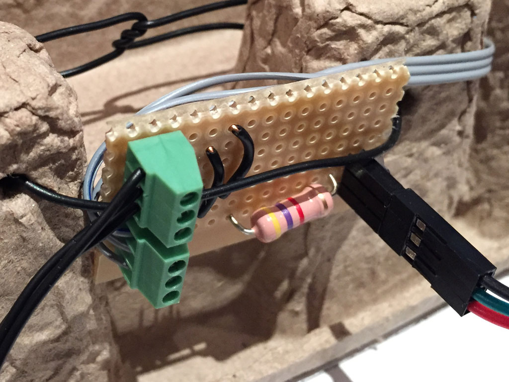
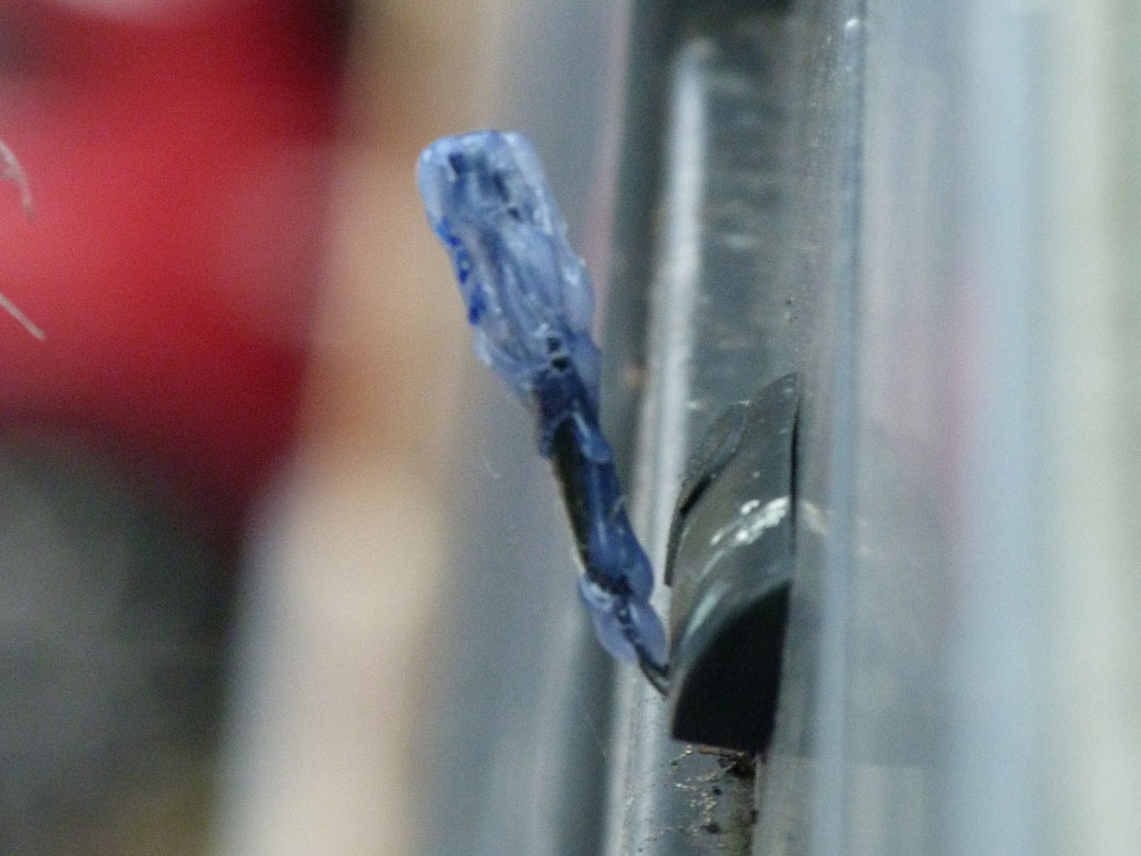
The indoor sensor was simple enough, but not having a waterproof variant of the DS18B20 sensor resulted in me creating one by soldering wires direct to the sensor, using heat shrink insulation on the pins and covering in hot glue to create a crude weatherproof version. This turned out well as the single strand wire allowed precise angling of the sensor to ensure it remained out of sunlight but not touching surfaces that were susceptible to sunlight heat.
A bit of cable management and it was put in place. Next up was to power it up and apply the code to provide the display.
This code is contained in a single .py file within the home folder of Debain, by entering sudonano display.py and entering the following:
from Adafruit_CharLCD import Adafruit_CharLCD
from subprocess import *
from time import sleep, strftime
from datetime import datetimeimport os
import time
import Adafruit_CharLCD as LCD# Raspberry Pi pin configuration:
lcd_rs = 27 # Note this might need to be changed to 21 for older revisi$
lcd_en = 22
lcd_d4 = 25
lcd_d5 = 24
lcd_d6 = 23
lcd_d7 = 18
lcd_backlight = 4# Define LCD column and row size for 16×2 LCD.
lcd_columns = 20
lcd_rows = 4# Initialize the LCD using the pins above.
lcd = LCD.Adafruit_CharLCD(lcd_rs, lcd_en, lcd_d4, lcd_d5, lcd_d6, lcd_d7,
lcd_columns, lcd_rows, lcd_backlight)# Print a welcome message to show script has started
lcd.message(‘James-Batchelor.com\n \n Starting up…’)# Wait 5 seconds
time.sleep(5.0)#—-Begin Loop—–
lcd.clear()
while 1:
#Read outdoor temperature
tempfile1 = open(“/sys/bus/w1/devices/28-000007f34893/w1_slave”)
thetext1 = tempfile1.read()
tempfile1.close()
tempdata1 = thetext1.split(“\n”)[1].split(” “)[9]
temperature1a = str (tempdata1[2:-3])
temperature1b = str (tempdata1[4:-2])
temperature1 = str ((temperature1a) + ‘.’ + (temperature1b))#Read indoor temperature
tempfile2 = open(“/sys/bus/w1/devices/28-000007f268b0/w1_slave”)
thetext2 = tempfile2.read()
tempfile2.close()
tempdata2 = thetext2.split(“\n”)[1].split(” “)[9]
temperature2a = str (tempdata2[2:-3])
temperature2b = str (tempdata2[4:-2])
temperature2 = str ((temperature2a) + ‘.’ + (temperature2b))#Read system temperature
cputempfile = os.popen(“/opt/vc/bin/vcgencmd measure_temp”)
cputemptext = cputempfile.read()
cputempfile.close()
cputemp = str (cputemptext[5:-3])#Read system CPU load
cpuloadfile = os.popen(“uptime | tail -c 17”)
cpuloadtext = cpuloadfile.read()
cpuloadfile.close()
cpuload = str (cpuloadtext[:-13])#Write to screen
lcd.clear()
lcd.message(datetime.now().strftime(‘%a %d%b%Y %H:%M\n’))
lcd.message(‘ Outdoor Temp: %s’ % ( temperature1 ) + ‘\n\n’ )
lcd.message(‘ Indoor Temp: %s’ % ( temperature2 ) + ‘\n\n\n’ )
lcd.message(‘RPi: T=%s’ % ( cputemp ) + ‘ L=%s’ % (cpuload) )
#Update screen every 20 seconds
sleep(20)
Ctrl O and Ctrl X to save, then the file was converted to executable by entering on the commnd line:
Sudo chmod +x display.py
The script will continuously run when started, but to make it start in the first instance, enter:
Sudo nano /etc/rc.local
In the file, enter the following at the end of the file, before the exit(0) line:
(sleep 1;sudo python /home/james/display.py)&
A quick reboot via sudo reboot and the script will update the display.
Modifications
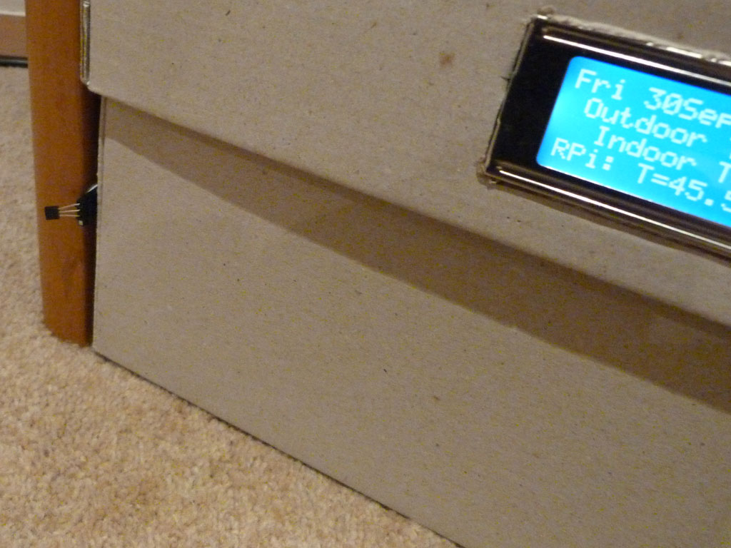
A check via various phone weather apps shows that the outside temperature was working great. However, the high indoor temperatures left me again sceptical. Luckily I had another Raspberry Pi and spare temperature sensors and found out I needed to move the indoor sensor further away from the case to provide more accurate readings.
So far its working great, but forever wanting more I’m currently researching how to send these temperature readings to a database in order to create graphs on daily temperatures. The Raspberry Pi community already has a host of different ways of achieving this, it’s just about picking the right one for me and implementing it to my needs.
Resources
LCD display code: Adafruit
Original temperature display code: REUK